My experience at Vitesco Technologies(Schaeffler Group ) as an Electronics Engineer
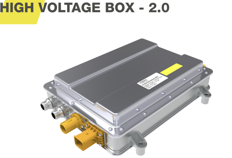
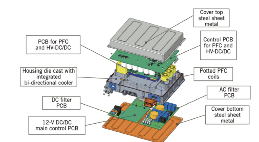
As part of my Master’s degree in Embedded Systems and Microsystems at the University of Toulouse III – Paul Sabatier, I completed a two-year apprenticeship at Vitesco Technologies in Toulouse, France. Vitesco Technologies is a global leader in electric-mobility solutions, I worked within the team developing the High-Voltage Box (HV Box), a system integrates an on-board charger (OBC) which contains all the electronic circuits required to recharge the electric vehicle’s battery, as well as the communication circuits between the vehicle and the charging stationand , the HV-Box also contains a high-voltage to low-voltage DC/DC converter for electric vehicles. On this page, I will describe the work I did at Vitesco Technologies, please note that detailed technical information will not be shared, as I am bound by an NDA.
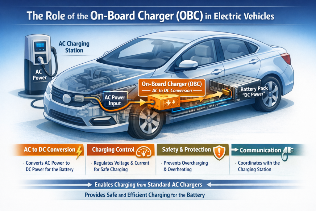
Why Electric Vehicles Need an On-Board Charger (OBC) Between the Battery and the Charging Station
Electric vehicles (EVs) are powered by high-voltage batteries that store energy in the form of direct current (DC) electricity. However, most public and home charging stations especially common “Level 1” and “Level 2” chargers deliver electricity as alternating current (AC). Because the battery cannot be charged directly using raw AC power, EVs require an important component called the On-Board Charger (OBC). The OBC is responsible for converting the electrical energy coming from the charging station into a form that the battery can safely store. Without the OBC, AC charging would not be possible in a modern electric vehicle. An OBC is placed inside the vehicle, and it acts as the “bridge” between the outside electrical network and the internal battery system. Its role goes far beyond simply converting current type. It ensures safety, controls power flow, manages charging quality, and protects the battery.
Most homes and many public charging points supply AC power, because AC is the standard form used by electrical grids. It is easier and cheaper to distribute over long distances, and it is what is available from wall outlets. That means EVs must convert this AC into DC before it reaches the battery.The OBC performs exactly this conversion using power electronics such as rectifiers, filters, and DC-DC converters. It transforms the incoming AC voltage into high-quality DC voltage that matches the battery’s requirements. Without the OBC, an EV could only charge from special stations that already provide DC (fast chargers), which would be inconvenient and expensive for most users.
In my first year, I mainly contributed to the system architecture of the OBC using Model Based Systems Engineering tools like Capella and System Composer, I was involved in the development of a system architecture model by creating a model that integrates all parts of the overall system, taking into account each subsystem’s functionality, cabling, and role within the HVBox. In the second year, my mission evolved toward modeling and simulating power electronic components in the HV Box, in order to better understand the charger’s efficiency, the behavior of its components and support design decisions. My role focused on modeling and simulating the energy losses that occur inside the charger, especially in the MOSFETs (switching and conduction losses), as well as diode conduction losses in the DC/DC converters. By developing simulation models in MATLAB/Simulink and LTspice, my goal was to estimate component losses during the battery-charging process, reduce the need for complex laboratory testing, and support the optimization of charger efficiency, the model will save money spent on testing and save time in the development of the HVboxes project.
MOSFETs are fundamental components used in electronic circuit design, where they are used to control electronic circuits. A MOSFET experiences both switching and conduction losses. Switching losses occur during the MOSFET’s ON–OFF transitions. Since a MOSFET does not switch instantaneously, there is a period during which both the current and voltage are non-zero, resulting in energy loss during the switching interval. In addition, energy is also dissipated during conduction.
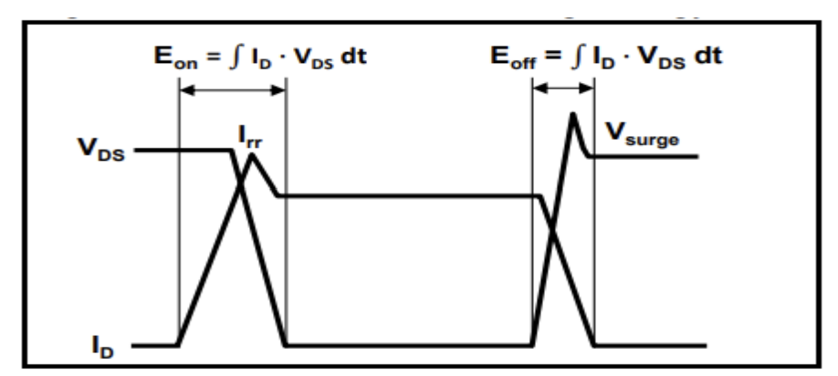
To calculate the switching losses, I began by gathering the information available in the datasheet provided by the manufacturer of the MOSFET used in the HVBox charger. This information allowed me to establish a starting point for the calculations. However, the datasheet curves alone were not sufficient to cover all of the converter’s operating conditions, so I created a switching-loss map based on LTspice simulations of the actual MOSFET model provided by the manufacturer.
By carefully designing a simulation circuit, I applied different combinations of drain current and drain-source voltage levels and measured the switching energy per event. After validating and scaling the results against the datasheet values, I built a two-dimensional lookup table of switching energy as a function of current and voltage. This lookup table was then imported into Simulink, allowing the model to compute switching energy dynamically during system-level simulation.